
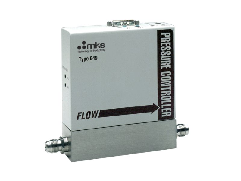
649B Downstream Pressure Controllers with Mass Flow Meter
Overview
The 649B upstream absolute pressure controller contains a Baratron® capacitance manometer, mass flow meter, normally-closed proportioning control valve, and closed-loop control electronics. The 649 controls absolute pressure. The patented mass flow sensor provides exceptional zero stability and accuracy of flow measurement. Full Scale ranges from 10 sccm to 5000 sccm nitrogen equivalent are available.
- Integral Baratron® capacitance manometer technology
- Patented mass flow sensor for exceptional long-term accuracy and zero stability
- Metal-sealed, cleanroom manufactured for critical high purity applications
- Fast response to set point with minimal overshoot
Products
Configuration Options
The following options are available for 649B Pressure Controllers with Integral Baratron® Manometer and Mass Flow Meter
Ordering Code Example: 649B00413T12C2VR
| Configuration Option | Option Code |
|---|---|
|
649B Pressure Controller with MFM |
649B |
Gas |
|
| Helium (He) | 001 |
| Argon (Ar) | 004 |
| Hydrogen (H |
007 |
| Nitrogen (N |
013 |
Pressure Range Full Scale |
|
| 10 Torr | 11T |
| 20 Torr | 21T |
| 50 Torr | 51T |
| 100 Torr | 12T |
| 1000 Torr | 13T |
Full Scale Flow Rate |
|
| 10 sccm | 11C |
| 20 sccm | 21C |
| 50 sccm | 51C |
| 100 sccm | 12C |
| 200 sccm | 22C |
| 500 sccm | 52C |
| 1000 sccm | 13C |
| 2000 sccm | 23C |
| 5000 sccm | 53C |
Orifice Size |
|
| A (50 sccm) | A |
| #1 (200 sccm) | 1 |
| #2 (1000 sccm) | 2 |
| #3 (5000 sccm) | 3 |
Plug Material |
|
| Viton | V |
| Kalrez | D |
| Metal | M |
| Kel-F | F |
Fittings (compatible with) |
|
| Swagelok 4 VCR male | R |
| Swagelok 8 VCR male | T |
Specifications
-
Type649 Pressure Controller with Capacitance Manometer and Mass Flow Meter
-
Pressure Range10, 20, 50, 100, 1000 mmHg (Torr) Full Scale
-
Valve Orifice50, 200, 1000, 5000 sccm (nominal Full Scale flow rates for N2 with 15 psig on inlet and atmospheric pressure on outlet)
-
Flow Rate10, 20, 50, 100, 200, 500, 1000, 2000, 5000 sccm (Full Scale)
-
Trip PointsPressure: Two open-collector transistors
Rated: 250 mA @ 30 VDC
Adjustable: 1 to 100% of Full Scale
Hysteresis: 3% of Full Scale
Indicators: Green LEDs on when actuated -
Pressure Control Accuracy±0.2% of Full Scale
-
Transducer Over Pressure Limit45 psia or 2x Full Scale, whichever is greater
-
Maximum Differential Pressure150 psi (consistent with transducer overpressure limit)
-
Control ModeDownstream
-
Pressure Measurement Accuracy±0.5% of Reading (includes linearity, hysteresis, and repeatability)
-
Zero Temperature Coefficient±0.04% of Full Scale/°C
-
Span Temperature Coefficient±0.04% of Reading/°C
-
Control Range2 to 100% of Full Scale
-
Typical Response Time1.0 sec (excluding system time constant)
-
Operating Temperature0 to 50°C (32 to 122°F)
-
Storage Temperature-20 to 80°C (-4 to 176°F)
-
Flow Measurement Range1% to 100% of Full Scale
-
Flow Repeatability±0.2% of Full Scale
-
Flow Resolution0.1% of Full Scale
-
Flow Accuracy±1.0% of Full Scale (including non-linearity, hysteresis, and non-repeatability referenced to 760 mmHg and 0°C)
-
Flow Span Temperature Coefficient< 0.08% of Reading/°C
-
Flow Zero Temperature Coefficient< 0.05% of Full Scale/°C
-
Flow Reading Pressure Coefficient<0.02% of Reading/psi
-
Input Power±15 VDC ±5%, 300 mA max.
-
Connector15-pin male Type “D"
-
Meter Response Time<100 msec
-
Meter Warm-up Time<2 min (within 0.2% of Full Scale steady state)
-
RFI SensitivitySAMA 33.1, 1-abc: <0.2% of Full Scale
-
Input-Output SignalsPressure: 0-10 VDC default (user settable to 0-5 VDC)
-
Cable Length100 ft. (30 m) max.
-
ComplianceCE
Features
Analog Operation
The 649 is powered by ±15 VDC at only 300 mA. The default pressure output and input control signals are 0-10 VDC. Two trip points are included in the 649, with LED status indicators, for use as simple on/off process limits. The 649’s control loop tuning parameters are preset for typical installation conditions, but are field adjustable for different conditions and optimum performance. The Proportional and Integral Term adjustments are simple rotary switches, providing a wide dynamic control range.
Control Loop
In the 649B, a pressure transducer monitors the pressure to be controlled at the downstream end of the controller. Actual pressure is compared in the electronics to the pressure set point signal. An appropriate signal is then generated to adjust the proportioning control valve to bring actual pressure into agreement with the desired set point. The internal control valve can be specified with one of four orifices allowing pressure control in systems with Full Scale flows from 10 sccm to 5 slm.
Resources
Literature
- 649B Compact Pressure Controller with Integral Baratron® Capacitance Manometer and Mass Flow Meter (197.1 kB, PDF)
Manuals
- 649B Compact Pressure Controller Manual (487.2 kB, PDF)
- 649 Pressure Controller Pin-outs (22.3 kB, PDF)
 Ultra-High Velocity