Sorry, this family of products is no longer available. For recommended replacements see upstream-pressure-controllers.

Dual-Zone Pressure Controllers with Mass Flow Meter
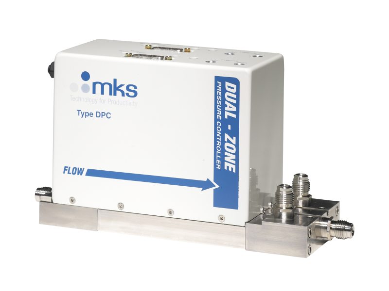
Overview
Specifications
-
TypeDual Pressure Controller
-
Control MethodAbsolute pressure capacitance manometer
-
Pressure Range10, 20, 50, 100 Torr
-
Fitting TypeSwagelok® 4 VCR® male compatible
-
Pressure Control Accuracy±0.5% of Reading
-
Transducer Over Pressure Limit45 psia or 200% Full Scale, whichever is greater
-
Control ModeAnalog Integral Adjustments: 10 positions (0 through 9)
Analog Proportional Adjustments: 10 positions (0 through 9) -
Zero Temperature CoefficientPressure: ≤0.02% Full Scale/°C
Flow: ≤0.05% Full Scale/°C -
Span Temperature CoefficientPressure: ≤0.04% Reading/°C
Flow: ≤0.08% Reading/°C -
Control Range10-100% Full Scale
-
Operating Temperature15 to 50°C (59 to 122°F)
-
Storage Temperature-20 to 80°C (-4 to 176°F)
-
Storage Humidity0 to 95% Relative Humidity, non-condensing
-
External Leak Integrity<10-9 scc/sec He
-
Leak Integrity Through Closed Valve<1% Full Scale
-
Flow Measurement Range10, 20, 50, 100 sccm
-
Maximum Inlet Pressure45 psia
-
Flow Accuracy±1.0% of Full Scale
-
Wetted Materials316L Stainless Steel, Inconel®, Nickel, Elgiloy®, Viton®
-
Surface FinishRa ≤10 µinches, electropolished
-
Set PointStability: ≤0.1% set point
Control Time to Set Point: ≤2.0 seconds (typical) -
Power RequiredDeviceNet: 11-25 VDC
Analog: ±15 VDC ±5%, 500 mA, maximum during first five seconds at start up, 400 mA at steady state -
Connector-InterfaceDeviceNet: 5-pin sealed microconnector with DeviceNet pin assignments
Analog: 15 pin D male (one per channel) -
DeviceNet Communication Rate125 - 500 Kbps (user selectable)
-
MAC ID SwitchesDeviceNet: 2, one for each pressure control channel (4 MAC ID switches)
-
IndicatorsDeviceNet: LED Network Status (green/red) LED Module Status (green/red)
-
Meter Warm-up Time1 hour
-
Stability at set point<0.1% set point
-
Input-Output SignalsAnalog Output: 0 to 5 VDC (flow), 0 to 10 VDC (pressure)
Analog Pressure Set Point Input: 0 to 10 VDC -
Cable Length100 feet (maximum)
-
Weight10.5 lbs. (4.8 Kg)
-
Dimensions10.46 in (including fittings) x 3.36 in x 5.35 in
26.56 cm (including fittings) x 8.53 cm x 13.59 cm
Resources
Literature
- DPC Dual-Zone Pressure Controller (443.2 kB, PDF)
Device Description Files
- DPC EDS File (18.3 kB, EDS)
 Ultra-High Velocity