Mass Flow Controller Module, DB9, 4 Channel
Model: AS11890G-11
Mass Flow Controller Module, DB9, 4 Channel

Mass Flow Controller Module, DB9, 4 Channel
Model: AS11890G-11
Overview
Overview
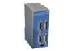
The AS11890G-11 Mass Flow Controller Module provides a compact and high density solution for integrating 9 pin analog mass flow controllers with the MKS Automation Platform PAC or CM modules. The MFC Module has a direct 1:1 pin mapping of the mass flow controller, so connected mass flow controllers that are fully powered and controlled through the MFC slice. Each MKS MFC Module supports integrating 4 MKS mass flow controllers.

Technical Specs
-
TypeMass Flow Controller Module
-
ADC Native Resolution14-bit
-
Auxiliary Power Supply24V ±5%, This input will be used to power MFCs connected through IO connector. Each power output to MFC should be protected separately.
-
Power ConsumptionAssuming each MFC consumes 250 mA and all AOs are fully loaded ≥24 V_IO@1.5 Amp, 24 V_CORE@ 0.15 Amp
-
Anti-alias HW Filtering200Hz ±20%, 6dB/octave minimum
-
Connector9 pin D-sub
-
Analog Input Minimum Input CMRR50dB, 0-1kHz
-
Analog Input Maximum Integral Non-linearity±2LSB (14-bit @ 14v)
-
Analog Input Number of AO Channels16, Single Ended, (4 for each MFC: Valve test point, Flow signal output, Optional input, Pressure output)
-
Analog Input Voltage Range-2V to 14V
-
Analog Input Maximum Error Over Full Range±0.05% of Full Scale (over 20°C - 30°C)
-
Analog Input Sampling Rate6.25 kHz (160µSec , for all 16 channels) (ADC oversampling is set to x32)
-
Analog Input ProtectionESD to IEC 61000-4-2 ±4kV contact, short to 24V, +15V, or -15V
-
Analog Output Number of AO Channels4 Single Ended (1 for each MFC: Set Point Input)
-
Analog Output DAC Native Resolution14-bit
-
Analog Output Maximum Output Current5mA, into a 2kOhm, 10nF load
-
Analog Output Output Accuracy at 25°C Ambient±0.1% of Full Scale @5v, ±0.05% of Full Scale @10v
-
Analog Output Settling Time±2.5mV in 1msec into 2kOhm, 10nF load
-
Analog Output ProtectionESD to IEC 61000-4-2 ±4kV contact, short to 24V, +15V, or -15V
-
Digital Output Maximum Voltage Drop when ON0.2V into 30 kOhm Impedance
-
Digital Output Number of DO Channels12 (3 for each MFC: valve open, valve close, flow zero)
-
Digital Output Maximum Leakage Current OFF30 µA
-
Digital Output Minimum available current ON6 mA
-
Digital Output Protection5V TVS, resettable Fuse (25 mA PTC)
-
Logic Level5V TTL tri state DO for valve override function, Active HIGH and LOW, HIGH opens MFC control valve, Low closes the valve and floating allows for set point to control, 5V TTL Active Low for valve close, Valve open or Flow zero functions referenced to signal ground
-
Minimum Input Impedance150 kOhm
-
TimingValve override 100 msec + response time (Digital Output)
-
Operating Temperature0 - 55°C
-
Storage Temperature-40 - 85°C
-
AltitudeUp to 2000 meters
-
Humidity5 - 85% non-condensing
-
Dimensions52.5 x 125 x 92.3 mm
-
MountingDIN rail
-
ComplianceCE
 Ultra-High Velocity