Ultrapure Water for Semiconductor Manufacturing
Semiconductor device manufacturing consumes large quantities of water for a variety of purposes ranging from equipment cooling to wafer surface cleaning. Low purity water requirements and conditioning will not be discussed in this overview. Rather, we will focus on the production of ultrapure water (UPW) for use in device fabrication processes. Ultrapure water is required for many process steps. Early stages of device fabrication require repeated steps for wafer cleaning, rinsing and surface conditioning. At many different stages in device manufacturing, it is used for surface cleaning, wet etch, solvent processing, and chemical mechanical planarization. Indeed, the latter unit process has become one of the largest consumers of UPW within the fab, requiring high volumes for slurry production and rinsing.
Large amounts of UPW are consumed in all fabs - according to the International Technology Roadmap for Semiconductors (ITRS) (2011), device fabs utilized 7 liters/cm2 of UPW per wafer out. This means that a typical 200 mm wafer fab that processes 20,000 wafers per month can use up to 3,000 m3 of UPW per day. That is the equivalent of the daily water requirements of a community of 20,000 people. The conversion of raw water to water of ultrahigh purity is thus a significant and costly activity for all semiconductor fabs. Because of the high cost of production and the high-volume needs, there are constant and significant efforts within the industry to reduce the usage of UPW. The ITRS usage target for 2020 was cited as 4.5 liters/cm2 in the 2015 ITRS Roadmap.
UPW is normally produced using reverse osmosis / deionised resin bed technologies; however, as device linewidths continue to shrink, the requirement for ever higher water purities in semiconductor applications is expected to increase beyond the capabilities of current production technologies. Indeed, modern semiconductor standards for ionic contaminants in UPW are so stringent that some analyses are beyond the detection limits of available analytical tools. This section, will provide the reader a basic familiarity with the design elements and functionalities for UPW systems. We will discuss the main UPW parameters, the treatment sequence for UPW and provide some details of the main treatment steps.
UPW Parameters
Several parameters are monitored for quality control of UPW. These parameters, their points of measurement and measurement method are identified in Table 1. A brief discussion of the main kinds of contaminants, methods of control of their level in UPW, and their typical specified limits is provided below.
| Parameter | Measured (POD/POC) | Test Method |
|---|---|---|
| TOC | Online | Conductivity/CO2 |
| Organic Ions | Lab | Ion Chromatography |
| Other Organics | Lab | LC-MS, GC-MS, LC-OCD |
| Total Silica | Lab | ICP-MS or GFAAS |
| Particle Monitoring | Online | Light Scatter |
| Particle Count | Lab | SEM - capture filter at various pore sizes |
| Cations, Anions, Metals | Lab | Ion Chromatography, ICP-MS |
| Dissolved O2 | Online | Electric Cell |
| Dissolved N2 | Online | Electric Cell |
- ICP-MS - inductively coupled plasma - mass spectrometry
- LC - liquid chromatography
- GC - gas chromatography
- MS - mass spectrometry
- SEM - scanning electron microscopy
- GFAAS - graphite furnace atomic absorption spectroscopy
- LC-OCD - liquid chromatography - organic carbon detection
Table 1. UPW Parameters, measurement points and methods.
Resistivity: This is measured in mega-ohm centimeters or Mohm-cm. Low ion contaminant concentrations in the UPW produce high resistivity values. The theoretical upper limit for UPW with zero ionic contamination is 18.25 Mohm-cm. The 2015 International Technology Roadmap for Semiconductor (ITRS) guideline for UPW resistivity at 25°C is >18.0 Mohm-cm.
Total Oxidizable Carbon (TOC): The TOC of UPW is measured in parts per billion (ppb). Oxidizable carbon in UPW originates from both inorganic (i.e., mineral carbonates) and organic (including biological and man-made contaminants) carbon contamination in the raw feed water. Typically, reverse osmosis (RO), ion exchange, UV irradiation and degasification are employed to reduce the TOC to acceptable levels in UPW. Tolerable TOC levels in UPW can vary, depending upon the application; however, most applications require very low carbon levels. As an example, the TOC levels needed to avoid lens hazing in immersion lithography have been a recent driver for this specification, with point of use levels of <1.0 ppb being specified for acceptable performance. The ITRS guideline for TOC is <1.0 ppb.
Dissolved Oxygen (DO): DO is measured using an electrochemical cell. Typically, DO levels in modern fabs are less than 5 ppb. Dissolved oxygen is removed from UPW using vacuum degasification in membrane contactor systems.
Particulate Matter: Raw water sources have high levels of particulate matter. Particles above the micron scale are removed using pre-filters and microfilters, after which the water is polished using increasingly fine filters to remove particles with diameters down to about 0.2 microns. Ultra-filtration at 10,000 molecular weight is used to remove residual particulates beyond this point. Particle specifications for UPW vary, depending on the fab application; in general, particles greater than 0.2 microns cannot be tolerated in any device fabrication, with well-defined limits on particle counts/liter for particles of smaller diameters down to around 0.05 microns. The current ITRS guideline for UPW is <0.3 particles/ml @ 0.05 micron particle diameter. Industry targets are ambitious; suggestions have been made for a specification of the order of <10 particles/ml having diameters greater than 10 nm, a specification that the industry is currently unable to measure, let alone control. In addition to particulate removal in bulk UPW, point of use (POU) ultrafiltration is often employed in the fab environment. Particle counts are normally measured using laser light scattering.
Bacteria: Some bacteria can survive the UPW treatment process and these pose both a biological and particulate threat to integrated devices. Bacterial adhesion occurs naturally in water as pipe walls attract minute quantities of organic nutrients, which attach to the wall and initiate the biofilm process. While regular sanitization programs are employed by some facilities and provide safeguards against microbial activity, biofilms can prove resistant and may permanently coat the inaccessible surfaces of valves and dead-legs. Proper system design and adequate flow velocity are more important than periodic sanitizations to maintaining cleanliness of the system.
Currently, the tests for bacteria and other organisms in UPW employ culture methods that test for viable bacteria and determine the level as "colony forming units/litre" or cfu/liter. These methods lack sensitivity in that only viable bacteria are recovered and large volumes of water may need to be sampled to provide adequate reliability (e.g. <1 cfu/liter cannot be measured with a 100 ml sample). A new technology called Scan RDI may offer a solution for testing total viable organisms. The method is able to detect a single cell based on direct measurements of cell activity and includes bacteria and other live organisms that may be present in biofilm. Another method for bacteria detection is epifluorescence, in which a technician uses a microscope to visually identify both viable and non-viable bacteria that have been stained with dyes that cause biological materials to fluoresce under ultraviolet light. A skilled microscopist can determine much qualitative and quantitative information about the bacteria in the UPW using this method. The ITRS recommended specification for bacterial contamination in UPW is <1 per 1000 ml (by culture).
Silica: Silica, normally measured in ppb, is present in the feed water to UPW systems as silicates and polymeric (or colloidal) silica. Gross removal of silica normally occurs in the RO step of water purification with final removal of residual silica accomplished using anion exchange resin beds followed by ultrafiltration. Typically, the limiting specification for total silica in UPW is 0.2 - 1.0 ppb for dissolved silicates and 0.3 - 2.0 ppb for colloidal silica.
Ions and Metals: Dissolved solids in the feed water to UPW systems consist of a charge-balanced mixture of cations (mostly metals) and anions. These impurities are removed in ion exchange resin beds. Acceptable concentrations of ions and metals in UPW range between 0.02 and 1 ppb, depending on the species and the application. UPW Unit Operations: Figure 1 provides a schematic of the unit operations in a typical UPW system.
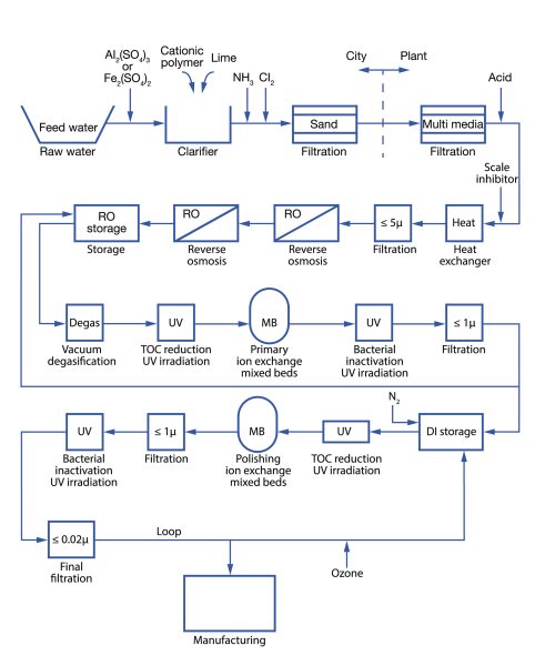
Figure 1. UPW water system process flow abstracted from Sematech guidelines.
Related Topics
Semiconductor Fab Utilities
- Semiconductor Fab Utilities Overview
- Semiconductor Gas Storage and Delivery
- Semiconductor Exhaust Gas Treatment
- Cleanroom Ultra-clean Air Delivery
Front-end Semiconductor
For additional insights into semiconductor topics like this, download our free MKS Instruments Handbook: Semiconductor Devices & Process Technology
Request a Handbook Ultra-High Velocity