Rebuilding an MKS 421, 422, or 431 Cold Cathode Sensor
Disassembly:
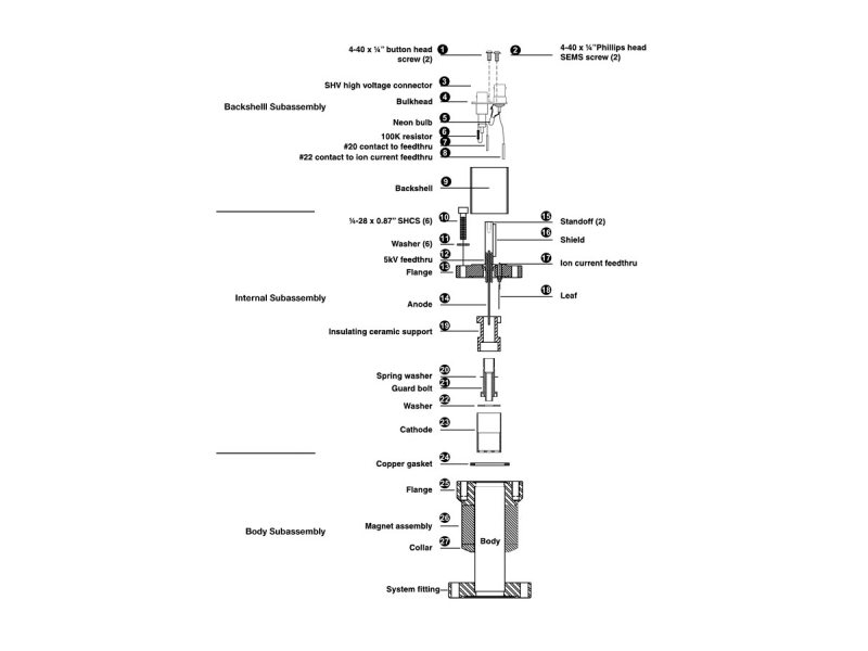
Cold Cathode Diagram
The Sensor breaks down into three subassemblies: the backshell, internal, and the body subassemblies. Only the internal and body subassemblies are exposed to vacuum.
To disassemble the Sensor, remove the backshell subassembly as follows (Steps 1 through 4 are not necessary when replacing internal parts):
- Remove the two 4-40 x 1/4 inch Phillips head SEMS screws and slide the backshell off the sensor.
- Remove the two 4-40 x 1/4 inch button head screws.
- Use needle nose pliers to pull the #22 contact off of the ion current feedthrough.
- Pull the #20 contact off the 5kV feedthrough taking the entire bulkhead with it (do not remove the SHV and SMA connectors from the bulkhead).
- Remove the six 1/4-28 x 0.87" (eight 10-32) socket head cap screws and pull the back flange free. Note that these screws are silver-plated for lubricity and should be used only once. They may be relubricated with a dry lubricant such as molybdenum disulfide, though new silver-plated screws are recommended. The copper gasket must be replaced. (The gasket has an O.D. of 1.29", an I.D. of 1.01" and fits a 2-1/8" CF.)
- The cathode and anode assemblies are attached to the back flange. Here disassembly generally proceeds from bottom to top of the internal assembly drawing.
- To remove the cathode, release the two integral, spring-loaded ears hooked over the shoulder of the ceramic insulating support.
- Gently pull up on the ear until it just clears the outer diameter of the insulating support.
- Slide the cathode and washer off the insulating support. Note the position of the small Elgiloy® leaf used to connect the ion current feedthrough to the cathode. Rotational position of the cathode with respect to the leaf is not critical, but take care to not bend the leaf.
- The insulating support is captured by the guard bolt. Remove with a spanner wrench (available from MKS) and unscrew the guard bolt from the flange. Note the presence of the small curved spring washer under the head of the guard bolt. The spring washer holds the insulating support tight, preloads the guard bolt to resist unscrewing due to possible system vibration, and provides compliance for differential thermal expansion during bakeout.
Cleaning the Sensor:
If ultrasonic cleaning, use high quality detergents compatible with aluminum, such as ALCONOx®. Scrubbing with mild abrasives can remove most contamination. Scotch-Brite™ or a fine emery cloth may be effective. Rinse with alcohol.
Clean aluminum and ceramic parts chemically in a wash, such as a 5 to 20% sodium hydroxide solution (not for semiconductor processing), at room temperature (20 degrees C) for one minute. Follow with a preliminary rinse of deionized water. Remove smut (the black residue left on aluminum parts) in a 50 to 70% nitric acid dip for about 5 minutes.
*Chemical cleaning should not be used to clean the anode; mild abrasives or ultrasonic cleaning are acceptable.
Do not damage the leaf spring while cleaning the Sensor.
Each of the above cleaning methods should be followed with multiple rinses of deionized water. Dry all internal components and the sensor body in a clean oven. The two ceramic spacers are slightly porous and will require longer drying time in the oven to drive off the absorbed water.
Assembling the Series 421 Sensor:
To reassemble, reverse the order used during disassembly. Note the following special tightening procedure of the guard bolt. The bolt has a 3/8"-40 thread, which is delicate.
- Finger tighten the guard bolt to compress the spring washer. Then back off tightness by a 1/2 turn. Do not overtighten as this will remove all compliance from the spring washer and possibly damage the aluminum thread.
- Verify that the anode is well centered within the bore of the guard bolt. If it is not, bend it back into position and continue with standard assembly.
Preparing the Sensor for Bakeout:
To prepare the Sensor for bakeout up to 125 degrees C, remove the high voltage and ion current cables only.
To prepare the Sensor for bakeout up to 250 degrees C, also remove the backshell and bulkhead subassembly shown in the diagram. Follow steps 1 through 4 of Disassembling the Series 421 Sensor (above).
Spare Parts:
- 100006734 Internal rebuild kit including copper gasket
- 100005462 Copper gasket 100005279 Spanner wrench
 Ultra-High Velocity