Isotropic Radical Etching
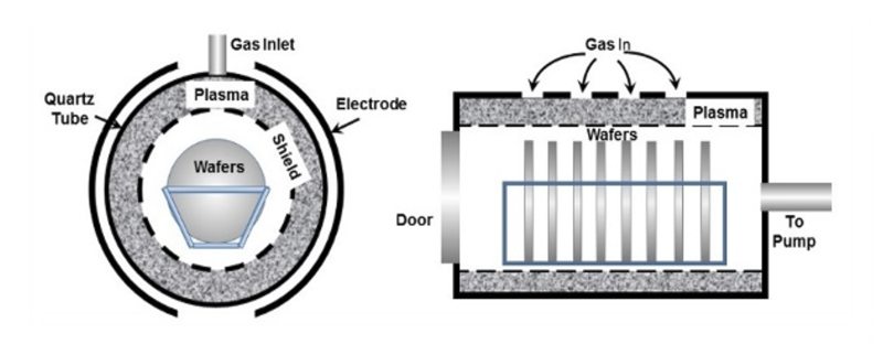
Figure 1. Schematic barrel etcher components.
High pressure plasma etching processes typically operate around 0.2 - 2 Torr. These are glow discharge methods that etch material via a chemical rather than a physical mechanism. The process pressures employed in plasma etching result in very low mean free paths for the ions generated in the plasma preventing any contribution from ion bombardment in the etching process. Thus, while plasma etching exhibits relatively good material selectivity, the purely chemical nature of the etching action results in primarily isotropic rather than anisotropic etching characteristics; this makes plasma etching of limited use in VLSI and ULSI device fabrication. So-called "barrel etchers" that use 13.56 MHz RF excitation are representative of this method. Barrel etchers are older technologies that were commonly used for photoresist strip, isotropic silicon nitride removal, silicon etching for solar cells, and plasma cleaning. Figure 1 shows a schematic of a barrel etcher. The etching process in these systems is fast and causes minimal substrate damage. As is shown in Figure 1, the plasma in a barrel etcher is created in an annulus between the shield and the RF electrodes which surrounds a quartz boat holding the substrate to be etched. A metallic shield protects the substrate from direct exposure to the plasma. Reactive neutrals diffuse through this shield to the substrate surface where they chemically react, removing material in the etching process.
More modern plasma etchers employ a parallel plate configuration that can be easily incorporated into mini-batch or single wafer process tools. Most configurations include the option of applying the RF bias to either the showerhead top electrode or to the substrate holder or both. This gives the user the choice of using simple, isotropic plasma etching (only the showerhead electrode is powered) or directional reactive ion etching (both the top and bottom electrodes are powered and the bias on the substrate attracts reactive ions - see Figure 2).
Figure 2. Plasma etch using remote sources.
The MKS remote plasma sources that are used in applications such as photoresist removal fall into the category of plasma etchers. In these configurations, the plasma chamber is removed from the substrate as shown in Figure 2. Remote positioning of the source ensures that only reactive neutrals reach the substrate. Ionic species and high energy electrons are destroyed before they can reach the substrate. This type of configuration guarantees minimal damage of the substrate due to ion and electron impact.
Related Topics
Semiconductor Etching
For additional insights into semiconductor topics like this, download our free MKS Instruments Handbook: Semiconductor Devices & Process Technology
Request a Handbook Ultra-High Velocity