Multi-gas, Multi-range, Elastomer-sealed, 5 - 50,000 sccm Mass Flow Controllers,
Overview
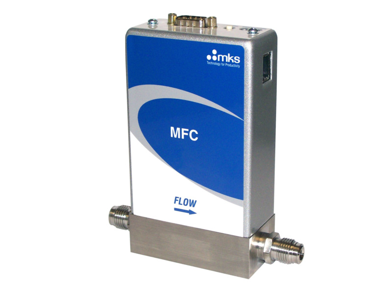
The G-Series GE50A digitally-controlled mass flow controller is available with either RS485, Profibus™, EtherCAT®, PROFINET, or DeviceNet™ I/O. The digital control electronics utilize the latest MKS control algorithms for fast and repeatable response to set point throughout the device control range. Typical response times are on the order of 500 milliseconds. Digital calibration yields 1% of set point accuracy on the calibration gas.
- Flow rates from 5 to 50,000 sccm
- Seal and valve plug options of Viton, Buna, Neoprene or Kalrez
- Wide choice of digital (EtherCAT, DeviceNet™, Profibus®, PROFINET and RS485) or analog (0-5 VDC or 4-20 mA) I/O
- Standard closed conductance leak rate of less than 0.1% of Full Scale
- Less than 750 millisecond settling time
Products
| Compare | Description | Drawings, CAD & Specs | Availability | Price | |||
|---|---|---|---|---|---|---|---|

|
GE50A013101RMV020 |
14 Weeks

|
$1,847 |
|
|||
|
|
GE50A013102RMV020 |
14 Weeks
|
$1,847 |
|
|||
|
|
GE50A013102SMV020 |
|
$1,847 |
|
|||
|
|
GE50A013103RMV020 |
14 Weeks
|
$1,847 |
|
|||
|
|
GE50A013103SMV020 |
|
$1,847 |
|
|||
|
|
GE50A013201RMV020 |
14 Weeks
|
$1,847 |
|
|||
|
|
GE50A013202RMV020 |
14 Weeks
|
$1,847 |
|
|||

|
GE50A013203RMV020 |
14 Weeks
|
$1,847 |
|
|||
|
|
GE50A013204RMV020 |
|
$1,847 |
|
|||
|
|
GE50A013204SMV020 |
|
$1,847 |
|
|||
|
|
GE50A013501RMV020 |
14 Weeks
|
$1,847 |
|
|||
|
|
GE50A013502RMV020 |
14 Weeks
|
$1,847 |
|
|||
|
|
GE50A013503RMV020 |
14 Weeks
|
$1,847 |
|
Configuration Options
The following options are available for GE50A Mass Flow Controllers
Ordering Code Example: GE50A013502R6V020
|
Configuration Option |
Option Code |
|---|---|
| GE50A Mass Flow Controller | GE50A |
Gas (Per Semi Standard E52-0703) |
|
| Nitrogen (N2) | 013 |
| Ammonia (NH3) | 029 |
| Sulfur Hexafluoride (SF6) | 110 |
| Other Gas Options | See Here |
Flow Range Full Scale |
|
| 5 sccm | 500 |
| 10 sccm | 101 |
| 20 sccm | 201 |
| 50 sccm | 501 |
| 100 sccm | 102 |
| 200 sccm | 202 |
| 500 sccm | 502 |
| 1000 sccm | 103 |
| 2000 sccm | 203 |
| 5000 sccm | 503 |
| 10000 sccm | 104 |
| 20000 sccm | 204 |
| 30000 sccm | 304 |
| 50000 sccm | 504 |
Fittings (compatible with) |
|
| Swagelok 4 VCR male | R |
| Swagelok 4 VCO male | G |
| 1/4'' Swagelok | S |
| Swagelok 8 VCR male | T |
| 1/8'' Swagelok | A |
| 1/2'' Swagelok | K |
| 6 mm Swagelok | M |
| 8 mm Swagelok | E |
| KF-16 | U |
| Swagelok 8 VCO Male | D |
| Swagelok 2 VCR Male | B |
| 10 mm Swagelok | P |
| 12 mm Swagelok | F |
| 3/8'' Swagelok | J |
| C-Seal | C |
Connector |
|
| EtherCAT | 8 |
| DeviceNet | 6 |
| RS485 (uses 9 pin connector) | 5 |
| Profibus (1480 Compatible) | 4 |
| Profibus (1179B Compatible) | 3 |
| PROFINET | 9 |
| Analog 0 to 5 VDC (9 pin D connector) | A |
| Analog 0 to 5 VDC (9 Pin D connector), Tied Grounds | L |
| Analog 0 to 5 VDC (15 pin D connector) | B |
| Analog 0 to 5 VDC (15 pin D connector), Tied Grounds | M |
| Analog 4 to 20 mA (15 pin D connector) | H |
Seal Materials |
|
| Viton | V |
| Buna-N | B |
| Neoprene | N |
| Kalrez | K |
| EPDM | E |
Valve/Device Type |
|
| Normally Closed | 0 |
| Normally Open | P |
Firmware |
|
| MKS will ship firmware revision current to date | 20 |
Specifications
-
TypeMass Flow Controller
-
Full Scale Flow Range5 - 50,000 sccm
-
Control Range2% to 100% of Full Scale
-
Seal MaterialViton, Buna-N, Neoprene, or Kalrez
-
Analog Connector9-pin or 15-pin D-subminiture
-
Maximum Inlet Pressure150 psig
-
Normal Operating Pressure Differential10 to 5000 sccm; 10 to 40 psid, 10000 to 20000 sccm; 15 to 40 psid, 30000 to 50000 sccm; 25 to 40 psid
-
Proof Pressure1000 psig
-
Burst Pressure1500 psig
-
Typical Accuracy±1% of set point for 20 to 100% Full Scale, ±0.2% of Full Scale for 2 to 20% Full Scale
-
Repeatability±0.3% of Reading
-
Resolution0.1% of Full Scale
-
Zero Temperature Coefficient<0.05% of Full Scale/°C
-
Span Temperature Coefficient<0.08% of Reading/°C
-
Inlet Pressure Coefficient<0.02% of Reading/psi
-
Typical Settling Time<750 msec, typical above 5% Full Scale
-
Warm-up Time30 minutes
-
Operating Temperature10°C to 50°C
-
Storage Humidity0 to 95% Relative Humidity, non-condensing
-
Storage Temperature-20° to 80°C
-
External Leak Integrity<1 x 10-09 (scc/sec He)
-
Leak Integrity Through Closed ValveUp to 10K valve <0.1% of FS at 40 psig to atmosphere, 20K - 50K valve <1.0% of FS at 40 psig to atmosphere
-
Wetted Materials316L S.S. VAR, 316 S.S., Elgiloy®, Nickel
-
Surface Finish16µ inch average Ra
-
Weight3 lbs (1.4 kg)
-
ComplianceCE
Features
Communication Options/Specifications
| Digital I/O | DeviceNet™ | RS485 | Profibus® | EtherCAT® | PROFINET® |
|---|---|---|---|---|---|
| Input Power Required | +11 to +25 VDC per (<2 watts) | +15 to +24 VDC (<2 watts) | +15 to +24 VDC (<2 watts) | +24 VDC (<3 watts) | +24 VDC (<3 watts) |
| Connector | 5 pin micro connector (power and comm.) | 9 pin Type D male (power and comm.) | 9 pin Type D male (power) 9 pin Type D female (comm.) |
2 x RJ-45 (comm.) male, M8 male, 5 pin (power) |
2 x RJ-45 (comm.) male, M8 male, 5 pin (power) |
| Data Rate Switch/Selection | 4 positions: 125, 250, 500K (Default) (programmable over network) |
No switch Set data rate via RS485 | No switch Set data rate via Profibus | No switch | No switch |
| Comm. Rate(s) | 125 Kbps; 250 Kbps; 500 Kbps | 9.6 Kbps; 19.2 Kbps 38.4 Kbps | 9.6 Kbps to 12 Mbps | 100 Mbps | 100 Mbps |
| MAC ID Switches/Addresses | 2 switches, 10 positions; 0,0 to 6,3 1 to 254 | Set address over RS485 Station Addresses 0,0 to 9,9 | 2 switches, 10 positions | 3 switches, 16 positions | N/A |
| Network Size | Up to 64 nodes | Up to 32 nodes | Up to 99 nodes | Up to 4095 nodes | N/A |
| Visual Indicators | LED Network (green/red) LED Module (green/red) |
LED Comm (yellow) LED Error (red) |
LED Comm (green/red) LED Error (green/red) |
LED Power (green) LED Run (green) LED Error (red) LED Comm (green) |
LED Maint (amber) LED BUS Fault (red) LED Ready (green) LED Sys Fault (red) |
| Compliance | CE | CE | CE | CE | CE |
Wide Choice of Digital and Analog Interfaces
The GE50A digitally controlled MFC is available with either analog or digital I/O. The digital control electronics utilize the latest in MKS control algorithms providing fast and repeatable response to set point throughout the device control range. Typical response times are on the order of 500 milliseconds. The GE50A’s analog and digital I/O can easily be used to replace those same I/O types of the 1179A MFCs. All GE50As include Modbus as an available secondary I/O (excludes PROFINET® and EtherCAT®).
Standard 3 inch Footprint
The GE50A utilizes the standard 3-inch footprint most often used by MFCs in the 5 sccm to 50 slm flow rate range enabling its use without the need to modify existing gas line configurations.
All Metal Wetted Surfaces
The design of the GE50A incorporates a minimal use of elastomers. There is only one external elastomer seal and elastomer valve plug. Otherwise, all wetted surfaces are of metal. The GE50A comes standard with Viton® seals along with options for Buna, Neoprene®, EPMD or Kalrez® allowing for the device’s use with gases requiring one of these alternatives
Percent of Setpoint Accuracy
Included digital calibration yields 1% of set point accuracy with N2 calibration gas for 20 to 100% of the full scale flow range. Set point accuracy enables precise process control vs accuracy stated relative to full scale. For mass flow rates of 2 to 20% full scale the accuracy is ±0.2% of full scale.
Embedded User Interface
An embedded user interface provides the ability to easily change device range and user gas which reduces inventory requirements. You can also monitor MFC functionality and collect performance data in-situ.
Patented Thermal Sensor
A well proven, patented thermal sensor design provides exceptional zero stability. US Patent No 5461913.
Mass Flow Controller Repair, Calibration & Evaluation:
MKS Service Solutions provide customers access to MKS certified repairs, original design engineers, complete product testing with original specifications found at no other repair center in the world. Our services testing often leads to predicting potential future issues which leads to equipment longevity.


Resources
Literature
- GE50A Elastomer-sealed, Digital Mass Flow Controller (449.5 kB, PDF)
Other
Application Notes
- Gas Delivery for Low-E Glass Coating Applications (530.2 kB, PDF)
- Gas Delivery for Plasma Spray Coating Applications (320.8 kB, PDF)
- MFCs for Gas Control in Case Hardening Processes (246.3 kB, PDF)
- Sample Gas Codes for Mass Flow Controllers/Meters
- Gas Correction Factors for Thermal-based Mass Flow
Manuals
- G and I Series Mass Flow Controller/Meter Manual (2.2 MB, PDF)
- G-Series Mass Flow Controller/Meter DeviceNet™ Supplement (112.5 kB, PDF)
- G-Series Mass Flow Controller/Meter RS485 Supplement (149.3 kB, PDF)
- G and I-Series Mass Flow Controller/Meter Profibus Manual Supplement (86.9 kB, PDF)
- G-Series Mass Flow Controller/Meter PROFINET Communications Supplement (1 MB, PDF)
- G-Series/I-Series MFC Modbus Register Map and Specification (502.9 kB, PDF)
- G-Series MFC Web Browser Tutorial (5.6 MB, PDF)
Drawings & CADs
- GE50A Mass Flow Controller 3D Model Files
- GE50 Mass Flow Controller Dimensional Drawing (1.9 MB, PDF)
Technical Notes
Device Description Files
- GE50A Profibus GSD File (1480 compatible) (2.6 kB, GSD)
- GE50A Profibus GSD File (1179B compatible) (2.5 kB, GSD)
- GE50A EDS File (346.2 kB, EDS)
- GE50A ESI File (132 kB, XML)


 Ultra-High Velocity